
IMT Weather Station (Si-RS485TC-2T-v-MB)
Overview
The IMT Weather Station model Si-RS485TC-2T-v-MB (referred to as the IMT sensor for the remainder of this article) is a high accuracy irradiance and cell temperature sensor. Optional attachments can be connected to monitor windspeed and ambient temperature. The IMT sensor is resold (not manufactured) and supported by eGauge Systems for use in applications where measuring irradiance may prove useful. The most common application would be to estimate solar production for an array of a given size using the irradiance and temperature data from the IMT sensor.
The IMT sensor communicates via Modbus RTU (RS485). A RS485 to USB adapter is required for use with the EG4xxx meter line, and a serial to Ethernet adapter is required for use with EG30xx meters. Instructions for using both adapters are included in this document.
If using multiple IMT weather stations on the same serial bus, the Modbus address must be changed. See the manufacturer's information at https://www.imt-solar.com/downloads/ under "Software Si-Series" for more information.
If splicing into a "wall wart" style DC power supply wires, verify the polarity of the DC output is correct with a voltmeter. Typically, the wire with a white stripe or dash is the positive line.
OEM Data Sheets
Visit https://www.imt-solar.com/ . Additional or newer version documents may be found in the "Downloads" section.
- Irradiance Sensor Main Unit Reference Guide (required for accessories)
- Irradiance Sensor Main Unit Data Sheet
- Wind Speed Sensor Data Sheet
- Ambient Temperature Sensor Data Sheet
Hardware Included
- IMT Weather Station (Si-RS485TC-2T-v-MB)
- Barrel connector to screw terminal block set
- 12Vdc power supply (120V American outlet wall-wart style)
Installation and Wiring
For best results, the IMT sensor must be installed in the same plane as the solar array. The sensor window should be clean and clear of any obstructions. Follow the mounting instructions included with the IMT sensor, and contact IMT directly with any questions regarding unique installation environments.
The IMT sensor has four wires and a heavier gauge wire shield connector. Depending on the application, the wire shield may or may not be used, and it is not shown in the following diagrams. If required, the wire shield should be connected to earth ground, not the RS485 ground or signal ground. Note that proper wiring is essential. Failure to wire the IMT sensor correctly will prevent the sensor from functioning and may cause damage.
Wiring for EG4xxx with RS485-USB adapter
The following diagram shows the IMT sensor connected to a 12Vdc power supply and RS485-USB adapter. The eGauge is not shown.
If splicing into a "wall wart" style DC power supply wires, verify the polarity of the DC output is correct with a voltmeter. Typically, the wire with a white stripe or dash is the positive line.
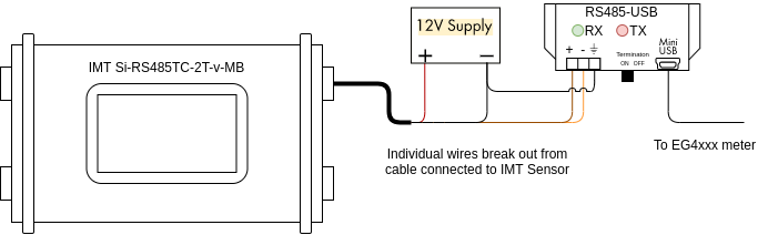
The wire assignments are as follows:
Black: Negative side of 12Vdc power supply
Red: Positive side of 12Vdc power supply
Orange: D- terminal on RS485-USB adapter
Brown: D+ terminal on RS485-USB adapter
The larger, thick black wire is a grounded shield and must not be connected to the eGauge, power supply or USB485 converter. Only connect this wire if you know what you are doing as improper grounding conditions can cause damage or communication issues.
Additionally, it is necessary to connect the ground (⏚) terminal on the RS485-USB adapter to the negative terminal of the 12Vdc power supply.
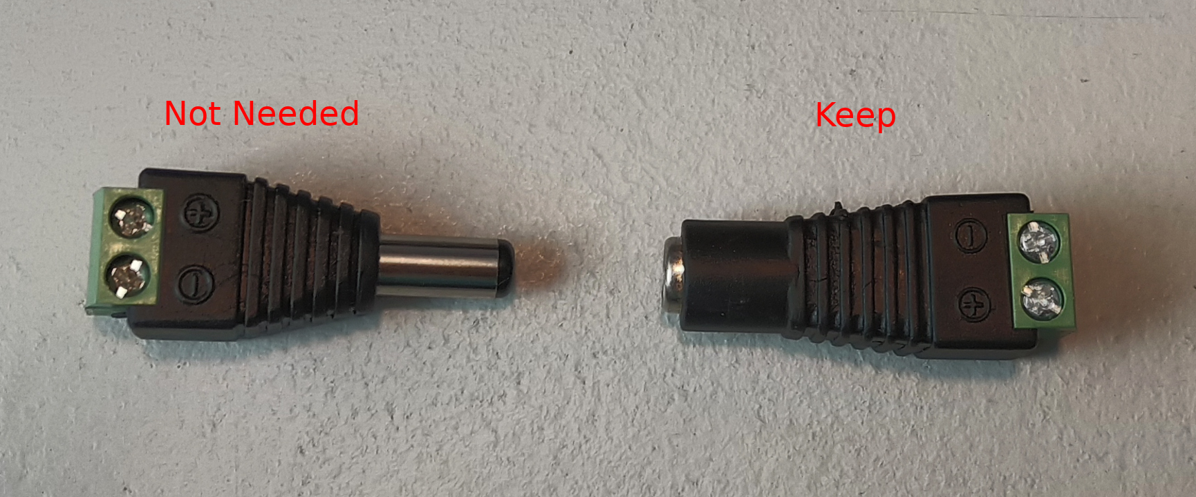
A barrel connector with terminal blocks is included with the IMT sensor. Use the female side to quickly connect the IMT sensor to the 12Vdc power supply without splicing any wires. The male side can be discarded or saved for use in another project.
Use the included USB cable to connect the RS485-USB adapter to the eGauge, and make a note of which port is used (USB1 or USB2). Also ensure the termination switch on the RS485-USB adapter is set to "ON".
Wiring for EG30xx using BF430 serial to Ethernet adapter
The following diagram shows the IMT sensor connected to a BF430 serial to Ethernet adapter. The eGauge is not shown.

The wire assignments are as follows:
Black: 9-30V-
Red: 9-30V+
Orange: RS485- terminal on BF430 adapter
Brown: RS485+ terminal on BF430 adapter
A note on power: The BF430 obtains power through a 9-30Vdc power supply, and can optionally share that power source with a connected device. As such, all four wires on the IMT sensor are connected to the BF430. However, note that the 12Vdc power supply provided by eGauge (or a similar 12Vdc power supply) should be used, as 9Vdc is too low for the IMT sensor.
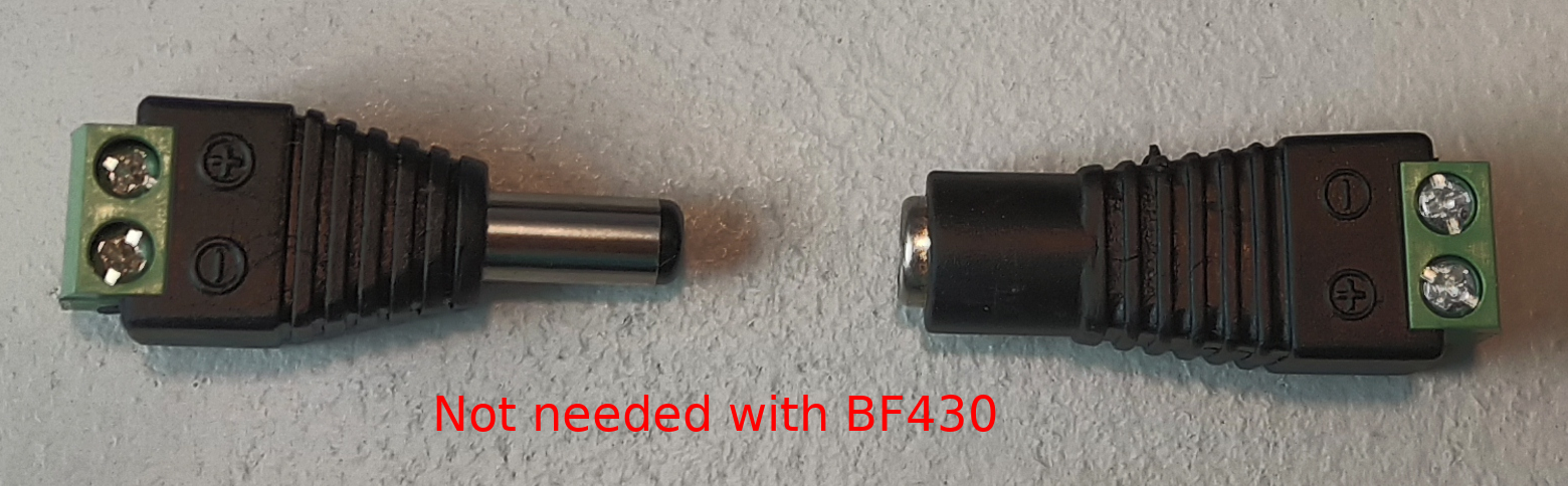
A barrel connector with terminal blocks is included with the IMT sensor, but it is not needed for this application. Discard this piece, or save it for another project.
Connect the BF430 to the same local area network as the eGauge, and ensure the external switch is set to "485".
Configuration
As a supported device, the IMT sensor has a predefined map built into the eGauge meter. This makes addressing and configuration very simple when using a RS485-USB adapter. Configuration with a BF430 is significantly more complex.
Valid credentials are required for the eGauge meter in order to make changes. See this article for more information.
Configuration for EG4xxx using RS485-USB adapter
The RS485-USB adapter does not require any configuration on the adapter side. However, it's important to note which USB port is in use by the adapter. It's also necessary to ensure the termination switch is set to "on" when used with the IMT sensor.

6. Click the grey "?" next to the device address field. After a few seconds, this should turn into a green check mark.
7. To save these settings, click the "Save" button at the bottom of the page.
If a red X appears instead of a green check mark, ensure the wiring is correct, the USB port is identified correctly, the address is entered correctly, and that the IMT sensor has power.
Assuming a green check mark is displayed, the next step is to configure the eGauge to store data from the IMT sensor. To do this, at least one register will need to be created.
1. Ensure a green check mark is shown next to the remote device address. If a grey "?" is shown, click it and wait for it to turn into a green check mark.
2. On the Installation page, navigate to the "Registers" section and click "Add Register".
3. Enter a suitable register name. This field is arbitrary, but should make sense to the end user.
4. The default register type will be set to "P". Click the dropdown menu and select the remote device name for the IMT sensor.
5. A second dropdown menu will appear. Select the remote register to record.
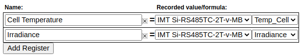
6. Repeat steps 2-5 for each remote register.
7. To save these settings, click the "Save" button at the bottom of the page. The meter will reboot.
8. Once the meter reboots, the RX and TX LEDs on the RS485-USB adapter should be blinking.
The IMT sensor has add-on hardware to measure ambient temperature and windspeed. These registers will be listed even if that hardware is not connected, but they will return invalid values if selected
Configuration for EG30xx with BF430 serial to Ethernet adapter
The BF430 requires additional configuration through its internal web interface. A computer with an Ethernet port and an Ethernet cable are required for configuration. The two primary areas of concern are applying the correct serial settings (listed below) and setting the BF430 to use either a dynamic IP address (obtained with DHCP) or a static IP address. Refer to the BF430 manual for additional information.
Support for the BF430 is limited. Using a RS485 to USB adapter is strongly recommended.
1. Ensure the BF430 is configured to use the following serial settings for RS485 communication: 9600 baud, 8 data bits, no parity, 1 stop bit.
2. Ensure the BF430 is set to obtain an IP address via DHCP or use an appropriate static IP address depending on the network requirements (generally, DHCP is preferred).
Once the BF430 has been configured and wired:

6. Click the grey "?" next to the device address field. After a few seconds, this should turn into a green check mark.
7. To save these settings, click the "Save" button at the bottom of the page.
If a red X appears instead of a green check mark, ensure the wiring is correct, the USB port is identified correctly, the address is entered correctly, and that the IMT sensor has power.
Assuming a green check mark is displayed, the next step is to configure the eGauge to store data from the IMT sensor. To do this, at least one register will need to be created.
1. Ensure a green check mark is shown next to the remote device address. If a grey "?" is shown, click it and wait for it to turn into a green check mark.
2. On the Installation page, navigate to the "Registers" section and click "Add Register".
3. Enter a suitable register name. This field is arbitrary, but should make sense to the end user.
4. The default register type will be set to "P". Click the dropdown menu and select the remote device name for the IMT sensor.
5. A second dropdown menu will appear. Select the remote register to record.
6. Repeat steps 2-5 for each remote register.
7. To save these settings, click the "Save" button at the bottom of the page. The meter will reboot.
8. Once the meter reboots, the RX and TX LEDs on the BF430 adapter should be blinking.
Viewing Data
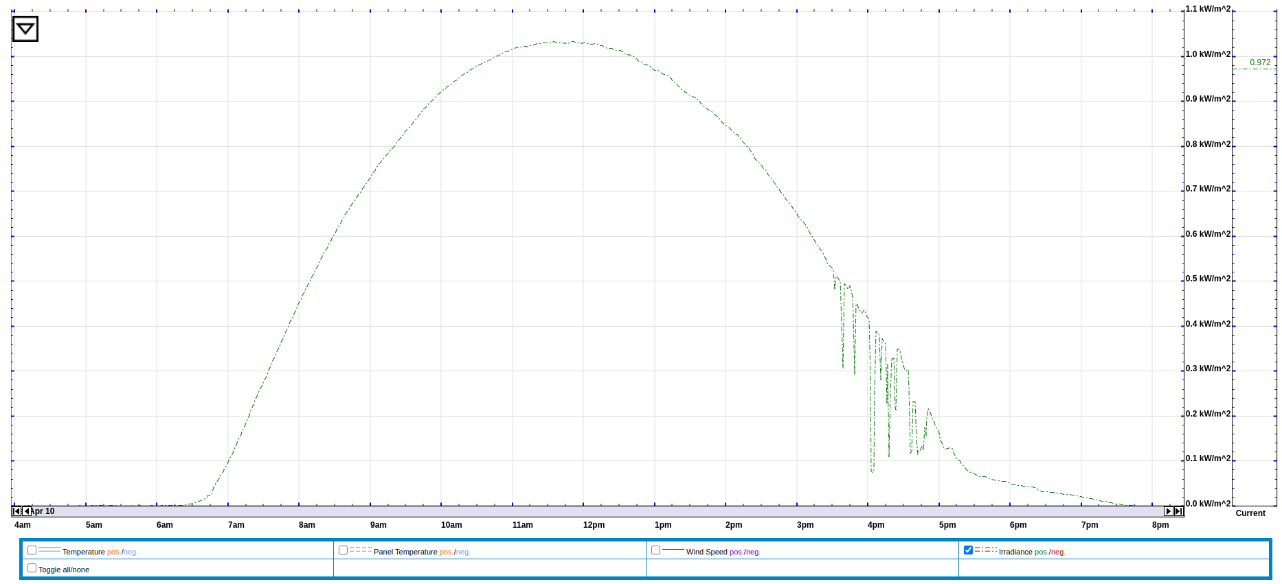
The data recorded from the IMT sensor can be viewed like any other data point recorded by the meter. To see this data, navigate to the main graph page and select the appropriate register(s) from the list under the main graph. In the following example, the graph is set to display irradiance data (with temperature and windspeed data as options under the main graph.
Data from the IMT sensor can also be used in formula registers to calculate the estimated solar production at a site. The formula for this calculation requires real time irradiance and temperature data (obtained from the IMT sensor), the array's rating in watts, and the panel temperature coefficient (usually a small negative number). The following example shows this formula based on a 10kW array and a temperature coefficient of -.12%.
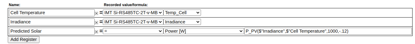
The formula field contains: P_PV($"Irradiance",$"Cell Temperature",10000,-.12)
Additional Sensors
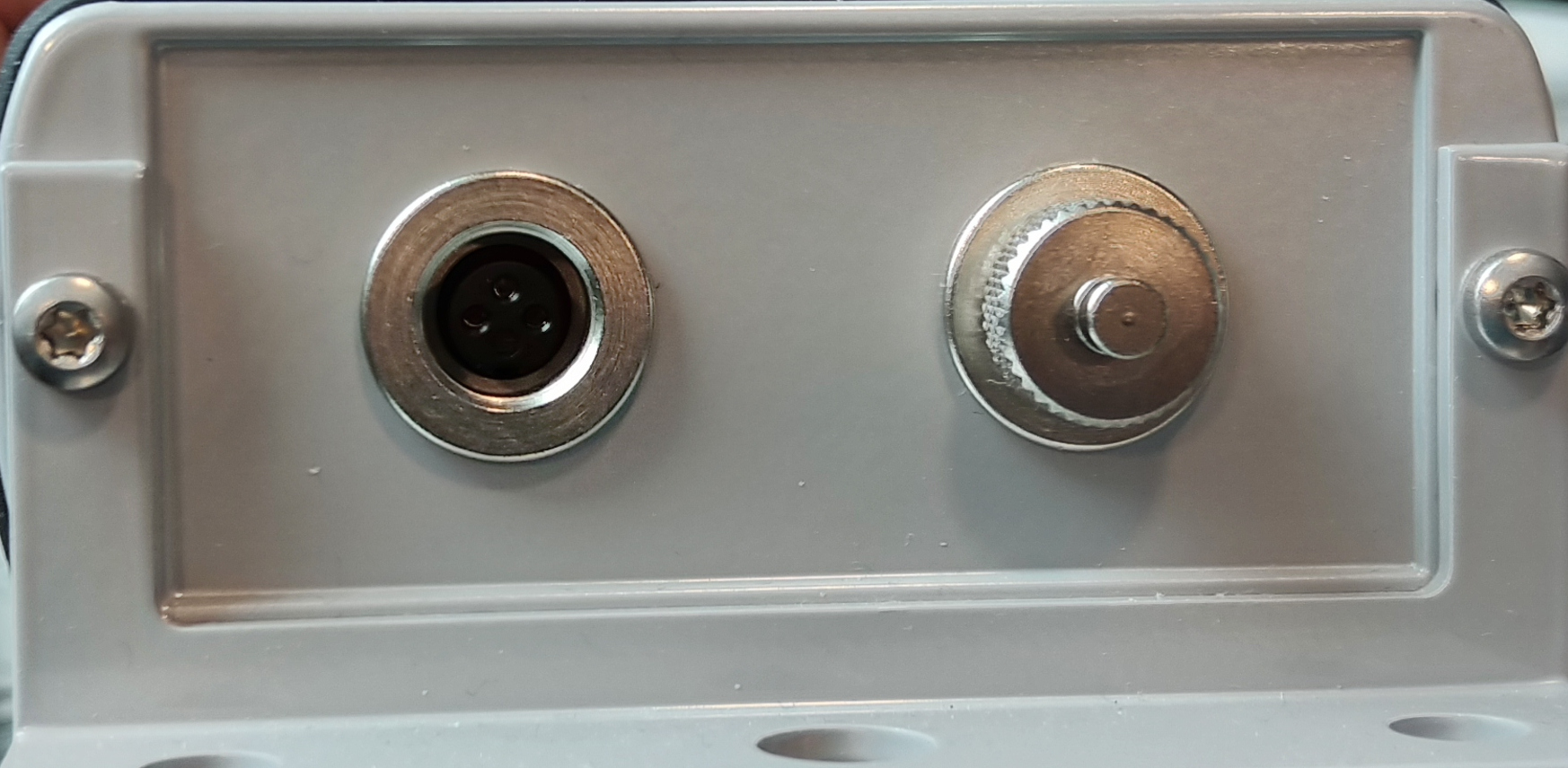
The IMT sensor supports two additional sensors: a wind speed sensor and an ambient temperature sensor. These sensors connect directly to the IMT sensor body. To connect these sensors, remove the appropriate threaded cap from the sensor body (the wind speed sensor uses the two pin connector, and the ambient temperature sensor uses the three pin connector). In the image below, one cap has been removed (left).
When using an add-on sensor, the configuration is exactly the same except additional registers will need to be created to record data from the add-on sensors.
Do not connect anything besides official IMT add-on sensors to these ports. Doing so will cause damage and void the warranty on the IMT sensor.
Suggested Reading
- RS485-USB adapter
- General information on connecting remote devices via RS485-USB adapter
- RS485-Ethernet adapter (BF430)
- Remote devices and third party devices