
Pulse Sensor (EPS)
Visit the online store page
Model: EPS
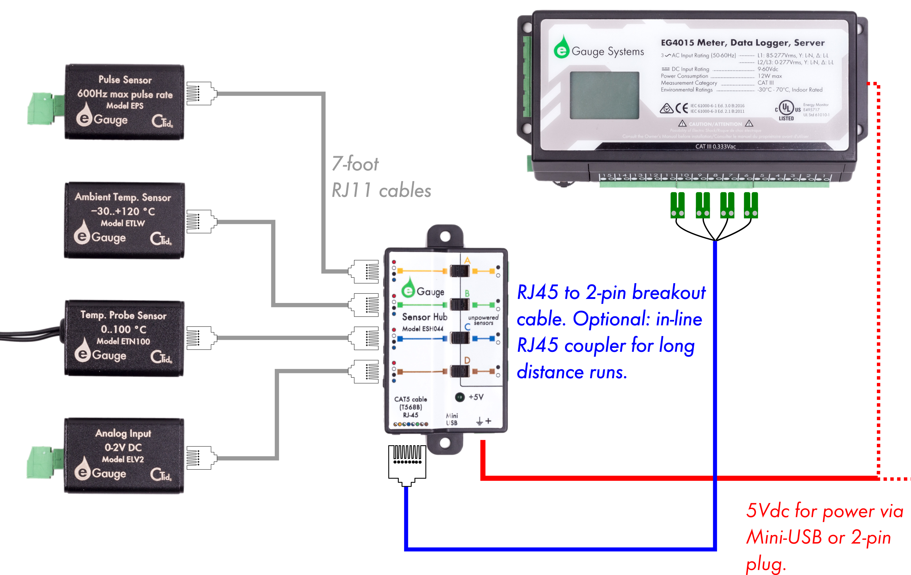
Requires the eGauge Sensor Hub and eGauge model EG4xxx (Pro or Core), not compatible with older model units.
Only use straight-through RJ-11 cables to connect powered sensors to the Sensor Hub. Telephone systems generally use "reverse" style RJ-11 cables which are incompatible with the Sensor Hub. See this article for more information on verifying the correct RJ-11 wiring. Every Sensor Hub compatible sensor sold by eGauge Systems comes with a straight-through RJ-11 cable.
The eGauge Pulse Sensor is used in conjunction with the Sensor Hub and an EG4xxx model meter (Core or Pro) to record pulse output data from devices such as water and gas meters. The Pulse Sensor can accept standard 2-wire pulse outputs or 3-wire 5-volt Hall effect pulse outputs.
See our Sensors product introduction video here.
 |
 |
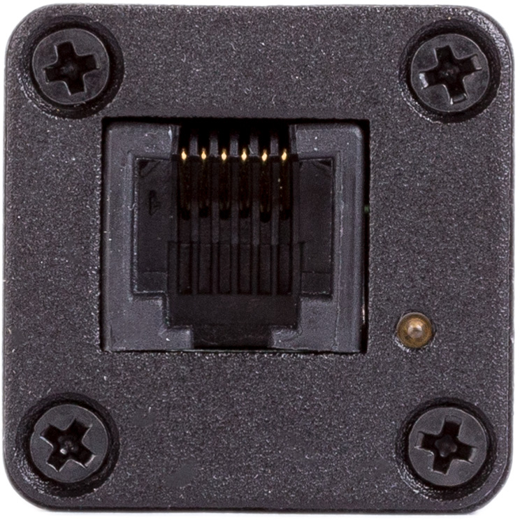 |
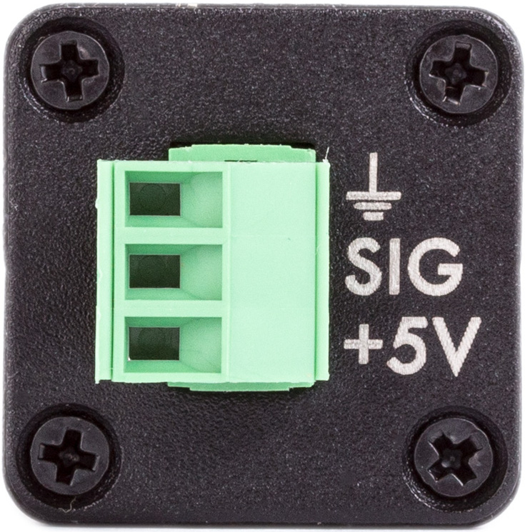
| Side view of EPS | Front view of EPS with connections | Back-side of EPS with RJ-11 port and CTid locator LED |
Specifications
Full specs (data-sheet PDF)
- CTid Enabled (w/ auto-configure and locator LED)
- Compatible with 2-wire pulse output and 3-wire 5-volt Hall effect pulse output
- Up to 600Hz max pulse rate
- 4.7 kΩ pull-up resistor between Signal and 2V
- Signal pin: open- 2V; closed- 0V
- -30 °C to 70 °C
- Humidity range: Up to 80%
- Extruded aluminum Case
- 26 x 26 x 40 (mm), 1.02 x 1.02 x 1.57 (in.)
- 7' RJ-11 cable for Sensor to Sensor Hub
- 47 CFR Part 15, Subpart B – Unintentional Radiators, Class B for Home or
Commercial use - US Patent # 10560763
- 2-year limited warranty
Hardware included
- 1x eGauge Pulse Sensor
- 1x 3-pin input plug
- 1x 7’ RJ-11 cable for connection to Sensor Hub
Assembly/installation information
- It is not advisable to extend the RJ11 leads from the Sensor to Sensor Hub. It is acceptable to use a longer RJ45 cable from the Sensor Hub to the eGauge.
- If RJ11 cable between Sensor and Sensor Hub must be extended, it is advisable to use twisted pair wires, such as a CAT5 cable with RJ11 plugs (most commonly used for DSL modems).
- If terminating own cables, both RJ11 and RJ45 cables should be straight-through cables, with the same color order on both ends.
- Install the sensors and Sensor Hub.
- Connect the EPS sensor to the pulse output using the signal and ground pins. If using a 5V hall effect sensor, the 5V pin may be utilized, otherwise it is left unused.
- Configure the sensors.
Note: Ensure the pulse sensor is configured for "normal value", not mean or frequency.

Documents
Related Information
Diagrams
2-Wire Pulse

3-Wire 5V Hall Effect

Typical Setup Overview
Advanced Diagnostics and Notes
Simulating Pulses
Pulses may be simulated on the EPS by shorting the Signal and Ground pins together. Any state change counts as a pulse, so connecting a wire between the Signal and Ground pins will count as one pulse, and removing the wire will count as a second pulse.
Viewing the Pulse Signal
The meter's Waveform View, in addition to viewing voltage and amperage waveforms, may also be used to view sensor inputs such as the EPS.
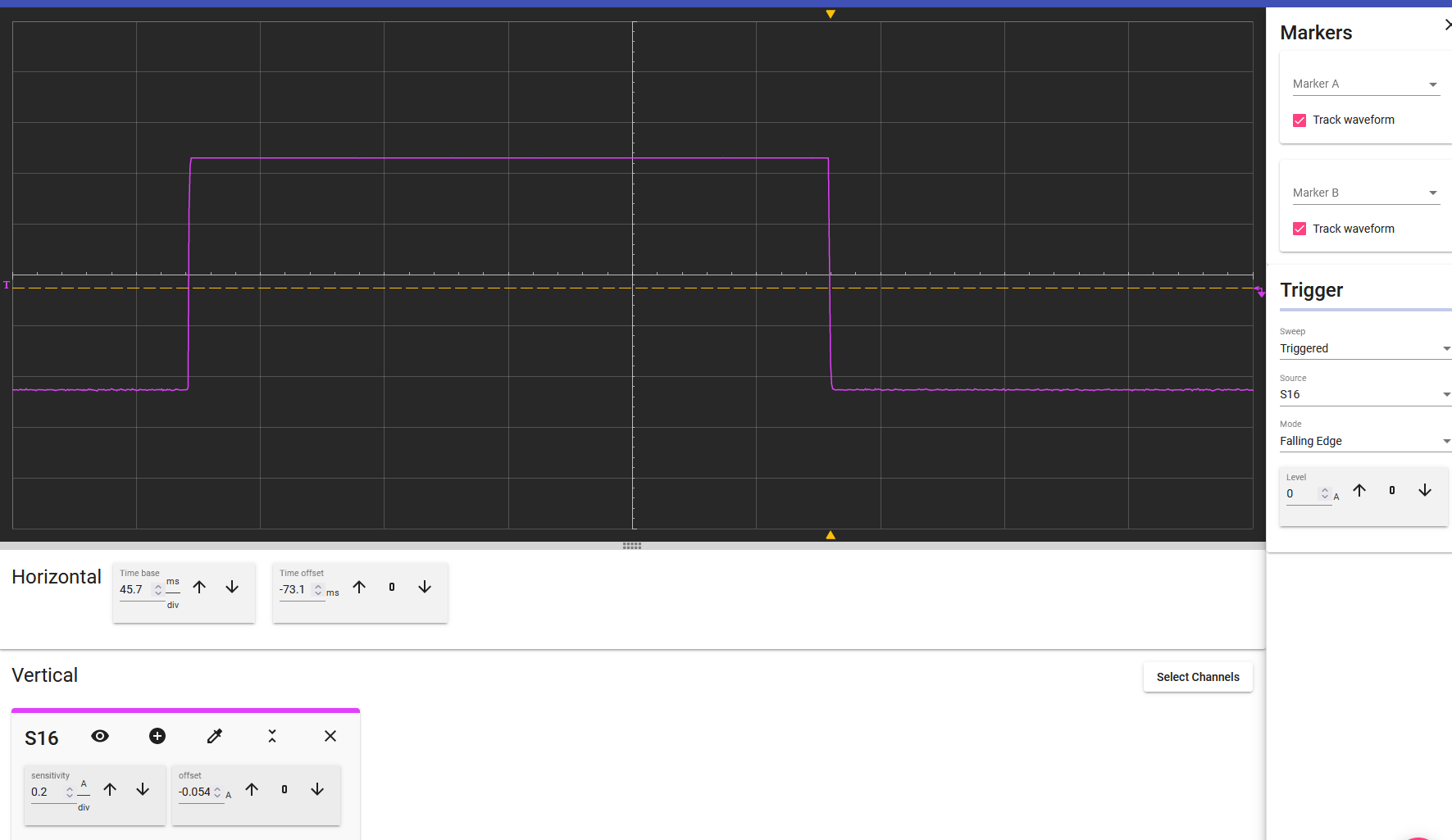
The above screenshot shows an EPS transitioning from open (low) state, to closed/shorted (high), back to open (low). Any transition, from low to high or high to low is counted as a single pulse. Thus, 2 pulses were counted during this capture.
The Horizontal controls show the time is 45.7ms per division, and the two state changes occur over approximately 5 divisions total, meaning 2 pulses were counted over the course of around 0.23 seconds (45.7ms * 5 divisions).
The EPS has a maximum resolution of 600 pulses per second.
Note the amplitude of the low and high states are around +/- 0.42 units (based off the sensitivity per division in the vertical sections).
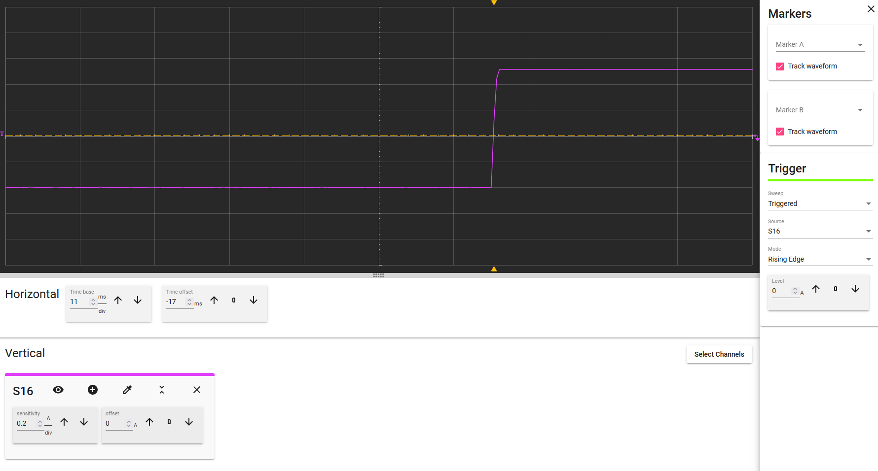
Similarly, the above Waveform view shows a single pulse, as the state transitions from low to high. When the next pulse occurs, the state changes from high to low and will count another pulse.